
Daewoo Trucks and Forklifts Service & Repair Manuals

General information
Engine characteristics
Main data and specifications
Engine specification(’98 type)
Engine performance curve
Exterior view of engine
Major maintenance
Preventive maintenance
Diagnostics and troubleshooting
for the engine
Disassembly and reassembly of major components
Disassembly
Inspection
Reassembly
Breaking-in
Scan pole diagnosis for DE12TIS
Wire harness connection
Sensor data
System & Vehicle selection
Actuator test
Self-diagnosis(current)
Flight record
Service Manual
G420E/G424E Tier LP Engine
Lift Trucks
G15S-2, G18S-2, G20SC-2
GC15S-2, GC18S-2, GC20SC-2
With G420E Tier LP Engine
G20E-3, G25E-3, G30E-3, G32E-3
GC20E-3, GC25E-3, GC30E-3, GC32E-3
with G424E Tier LP Engine
LPG AND LPG FUEL TANKS
ENGINE SPECIFICATION
MI-04 LPG SYSTEM OPERATIONAL OVERVIEW
MI-04 MAINTENANCE SCHEDULE
MI-04 LP BASIC TROUBLESHOOTING
MI-04 LP ADVANCED DIAGNOSTICS
MI-04 ELECTRICAL CONNECTIONS
N2001 PRESSURE REGULATOR /CONVERTER
N-CA55-500TR AIR/FUEL MIXER
TEST AND ADJUSTMENTS
SERVICE TOOL KIT
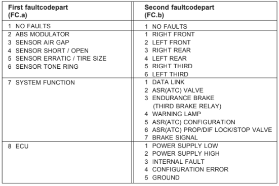
FAULTCODES / REPAIR INSTRUCTIONS
2. n Check modulator wires. Inlet(EV) or outlet(AV) or common wire is permanently or
temporarily broken or shorted to plus respectively ground.
3. n Amplitude of sensorsignal is to low. Check bearing play, polewheel run out, push sensor
to polewheel. Check sensor wiring and connectors for intermittent contact. Other possible
reason:gear engaged at slippery conditions. 16 sec. slip duration.
4. n Check sensor wiring. Open circuit, short circuit to plus respectively ground or between
sensorwires IG/IGM is detected
5. n Check sensor wiring and connectors for intermittent contact. Check toothed wheel for
damages. Check for mismatch-fault of another sensor. Pneus or number of polewheel
teeth are different.
6. n Check polewheel for damages/missing teeth/run out. Use WABCO sensor probe. Replace
polewheel if not checked o. k. If additional airgap faults are stored, adjust airgap.
7-1 ECU with PROP : Check wire and speedometer signal. C3/B7 signal calibration, check
tyre sizes.
Gear switch signals neutral or is manipulated.
Electronic engine control: Check wiring respectively other ECU's
Excessive slip / dynotester ? One axle was much faster than other?
7-2 Check wire. Output wire is interrupted or grounded or shorted to battery supply.
Check wire. Output wire is interrupted or grounded or shorted to battery supply.
ECU with SAE J1922 resp. SAE J1939:Check other ECU's. No access to the link
7-3
7-4 Check wire and bulb. Was blinkcode switch activated longer than 16 s?
Check wires resp. parametersetting. Diff-brake valve without engine control is detected or
CAN, PWM, PROP are detected while selfparameterizing is disabled.
7-5
7-6 Check wire. Output wire is interrupted or shorted to ground or battery supply.
7-7 Check brake sensor wiring. Intput wire is interrupted or shorted to ground or battery supply.
8-1 Check supply wire and fuse. Supply voltage is temporarily too low
8-2 Check alternator and battery. Supply voltage too high for more than 5 sec.
8-3 Replace ABS(ASR) electronic if fault detection repeats.
8-4 No modulators connected or wrong ECM or wrong parameterized
8-5 Check ECU ground wires and common modulator wires
BLINKCODE LIST
SERVICE ELECTRIC EQUIPMENTS FOR USER CIRCUIT DIAGRAM

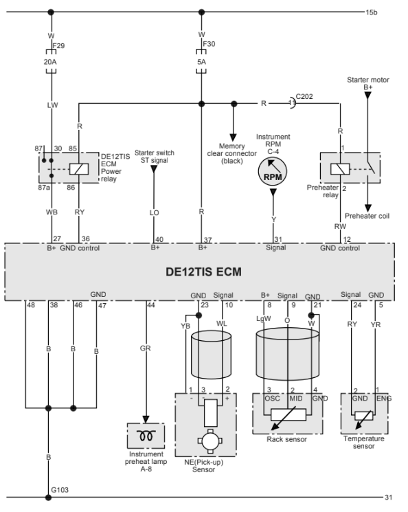
DE12TIS ECM POWER, RACK SENSOR, RPM SENSORCIRCUIT DIAGRAM
DAEWOO CONNECTOR AND PIN NUMBER
