Massey Ferguson Electrical Wiring Diagram
Massey Ferguson Service MF-7200 BETA Series MF-7260 BETA MF-7260 AL-4 BETA MF 7270 BETA MF-7270-AL-4 BETA

ELECTRICAL COMPONENT UNIT
- General information
- General description of components used in various electrical governing bodies
- Multi-function lever
- Hydrostatic pump
- Concave Reduction Motors
- Operating control valve
- Electro-hydraulic activation
- SISU engine
- Connector of the characteristics monitor and on-board computer
- Cab connector
- Manual control of the vertical position of the header
- Reel vertical position control
- Reel horizontal position control
- Discharge pipe position control
- Control of the reel speed variator
- Controlling the position of the MCS grille and fan variator
- Terra Control System
- Management of multifunctional light indicators
- Controlling the grain tank filling and shaft speed
- Electrical system of lighting equipment
- Leveling Electrical System, Models 5AL - 6AL
- Shutdown of the additional cylinder
- Straw Cutter Spreader Control
Electric control units
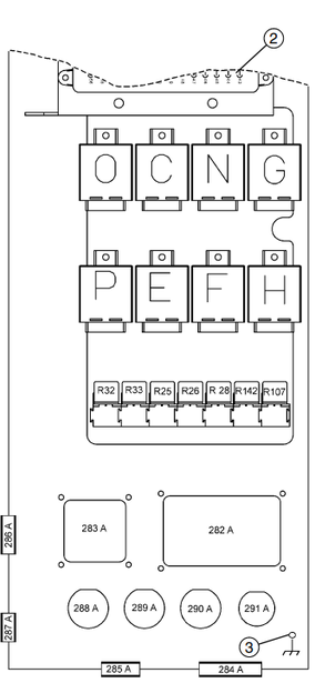
O Relay switch control computer
discharge pipe position, light operation
general accident indicator and reel movement
back.
C relay control ECU monitoring
reel vertical position,
power limiter solenoid valve
hydraulics and solenoid valve
shutdown of the hydraulic accumulator in the circuit
adjust the vertical position of the header.
N Relay switch control computer
manual control of the vertical position of the header
and the movement reeled forward.
G Relay ECU - header positioning control.
P Relay control ECU used to
optimization of the Terra-Control system (models
5AL - 6AL).
E The diode ECU monitors the control signals,
directed to the solenoid valve NO
working control valve.
F See paragraph E.
H The computer controls the electro-hydraulic control.
Additional relay switches
R25 Emergency Relay Switch ON
alarms for shaft speed and relay
switches R 6, R 11 and R 17.
R26 Relay alarm relay
straw choppers as well as on / off
straw choppers.
R28 Relay switch to enable emergency
sound alarm when reaching
the maximum level of filling the grain tank.
R32 System enable relay
concave adjustments.
R33 Relay switch to turn on the system
alignment.
R107 Relay start and start relay
signal of not disconnected hand brake.
R142 Relay switch for reversing lights
and lifting the header (with attached system
Terra-Control).
Connectors of the main body.
2 Fuse box and relay switch.
3 Ground connection screw.
282A Dashboard cable connector
283A Lighting cable connector
equipment.
284A Main power cable connector.
285A Electro-hydraulic cable connector
management.
286A Light-alarm cable connector.
287A On-board computer and system cable connector
Terra-Control.
288A Alignment system cable connector.
289A Cab cable connector.
290A Operating control valve connector.
291A Power Cord Connector.

1. Protective cover
4. Protective cover
5. Prefabricated housing covers
Connectors of the main body.

Additional relay switches
Connector removal

MAIN RELAY SWITCHES
The main machine relays are located
in two blocks (1 and 2) installed
inside the cabinet
on the right side of the cab.
Relay switches
DESCRIPTION OF MONITORED CHAINS
R1
R2
R3
R4
R5
R6
R7
R8
R9
R10
R11
R12
R13
R14
R15
R16
R17
R18
R19
R20
R21
R22
Alarm block for transmission control system of the cleaning unit.
Alarm block for under-hammer equipment speed control system.
Alarm block for straw chopper control system.
Alarm block for drum separator speed control system.
Relays for longitudinal alignment control (5AL and 6AL models only).
Relay switch for activating beater speed control systems, fans
and reel (with the engine running and the thresher control switch on).
Auxiliary relay switch to ensure the operation of fuses 2,3, 4, 5 and 6.
Relays for controlling straw choppers.
Relay switch to interrupt engine start when the electro-hydraulic
equipment.
Relays for automatic control of longitudinal alignment (only for models 5AL and 6AL).
Relay switch to control the increase in reel speed.
Relay switch to activate header lowering system using electrical Terra-Control, only with the engine running.
Relay switch for engine operation.
Relay switch for brake control system.
Auxiliary relay switch for fuse operation 40, 41 and 42.
Relay switch, electrical grid control
universal triera and for electric control of straw baffles cross sections (if installed).
Relay for controlling reel speed reduction.
Relay switch for rotating beacon control system
grain hopper.
Auxiliary relay switch for fuse operation
52, 53, 54 and 55.
Horn relay.
Flashing lights.
Hectare counter timer (5AL and 6AL models only).
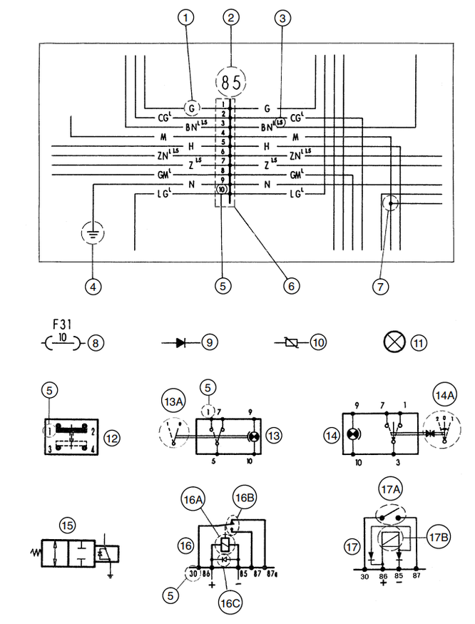
1. Cable color
2. Link to the part specified in the description of the circuit
3. Cable cross-section, in mm2 (cables, the size of which is not indicated, have a cross-section of 1 mm2)
4. Connection with the "mass"
5. The location of the cables in the connectors, sockets, switches, relays, etc.
6. Connector
7. Point with one-piece connection
8. Fuse No. 31 with a rating of 10 A
9. Diode
10. Varistor
11. Lamp, indicator light, warning light, etc.
12. Microswitch
13. Switch or control switch
13A. Switch positions
14. Rocker switch
14A. Rocker Switch Positions
15. Solenoid valve
16. Relays with protective diode
16A. Relay drive solenoid (attached to terminals 85 and 86)
16B. Relay contacts (connected to terminals 30 - 87 - 87a)
16C. Magnet protection diode
17. Relays with a double protective diode
17A. Relay contacts (connected to pins 30 and 87)
17B. Relay drive solenoid (attached to terminals 85 and 86)
NOTE: - if the components are shown in the diagrams in the locked position, then when removing
component it will be in this position.
- Always use relays with protective diodes and with characteristics,
corresponding relay functions.
- Do not reverse the polarity of terminals 85 and 86.
LETTER DESIGNATION OF COLOR FLOWERS
A = Blue B = White C = Orange G = Yellow
H = Gray L = Blue M = Brown N = Black
R = Red S = Pink V = Green Z = Purple